











Grading Tool Question
I am no grading estimator. But now because of awesome developers at ZZ I'm trying to expand our GC Estimating in more details.
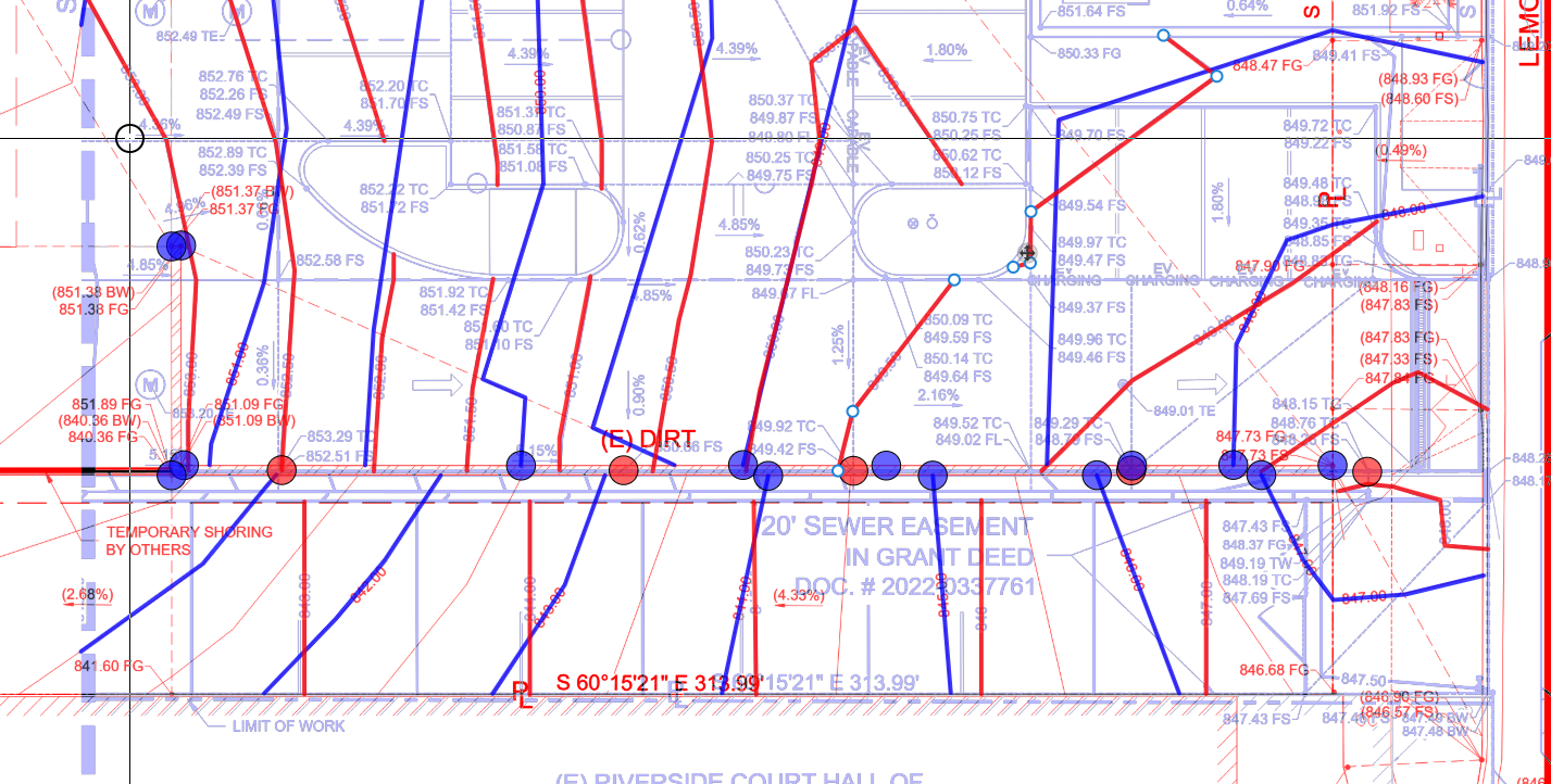
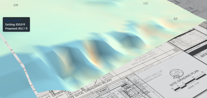
I am tracing contours of existing and new at (E) retaining wall area. I am not sure what I am missing, but my 3D visual is not identifying a vertical cut at the retaining wall location.

Hi Andy,
Why the wall disappears in 3D
The grading engine builds two smooth surfaces (existing and proposed) by interpolating between every contour and spot elevation it finds, on a grid (the "Grid" slider in the 3D parameters, default 2 ft). Interpolation is great at rolling terrain, but a retaining wall is a vertical discontinuity — the ground is at two different elevations at nearly the same spot. Contours alone can't express that: at a true vertical face the contour lines stack directly on top of each other, and when the plan (or the trace) spreads them apart even a little, the engine reads that as a steep slope and rounds it over. On top of that, the surface can only get as steep as one grid cell allows — with a 2 ft grid, a wall reads as a ramp about 2 ft wide, which the 3D view then shades smoothly. So a smooth hillside where the wall should be is the tool faithfully interpolating the data it was given, not losing it.
How to make the wall show up
- Pinch the data at the wall face. Trace the top-of-wall and bottom-of-wall as two contours (or two runs of spot elevations) placed as close together as you can draw them — inches apart on the plan, one pair on each surface that has the wall (for an (E) wall, at minimum the Existing surface: a top-of-wall line at the upper grade and a bottom-of-wall line at the lower grade, hugging the wall line). The elevation jump then happens over a tiny horizontal distance and the interpolator has no room to round it off.
- Tighten the grid. In the 3D parameters, drop the Grid slider to 1 ft (or the minimum) for this view. The face can never be narrower than one grid cell, so a finer grid means a visibly steeper, cleaner break. It costs a little render time on big sites but is worth it around walls.
- If it's actually an excavation you're modeling — a shored vertical cut rather than terrain — use the Cut Area tool in the Grading Toolbox instead of contours. A Cut Area with a "cut depth in feet" value produces true vertical walls by default (and battered walls if you set "side slope"), so it's the right tool any place you need a guaranteed sheer face, like the temporary-shoring zone on this plan.
Also specifically for this site: their tooltip shows Existing 850.9 / Proposed 852.1 at that spot — about 1.2 ft of fill — so if the wall stays and they're grading up behind it, the pinched-contour approach on both surfaces is the one they want; the Cut Area tool is only for the shoring/excavation scenario.
I hope this explanation helps
%22%2F%3E%3Ctext%20x%3D%2232%22%20y%3D%2233%22%20text-anchor%3D%22middle%22%20dominant-baseline%3D%22central%22%20font-family%3D%22Arial%2C%20sans-serif%22%20font-size%3D%2226%22%20font-weight%3D%22600%22%20fill%3D%22%23fff%22%3EMM%3C%2Ftext%3E%3C%2Fsvg%3E "Mark Monteiro")
Andy,
I do grading takeoffs. What you really need for retaining walls and curbs is a sloping line. I do not think that's available here yet. You also want to trim your contours so they do not run through the wall or curb.
%22%2F%3E%3Ctext%20x%3D%2232%22%20y%3D%2233%22%20text-anchor%3D%22middle%22%20dominant-baseline%3D%22central%22%20font-family%3D%22Arial%2C%20sans-serif%22%20font-size%3D%2226%22%20font-weight%3D%22600%22%20fill%3D%22%23fff%22%3EAK%3C%2Ftext%3E%3C%2Fsvg%3E "Andy Kansara")
Understood. Thanks Todd and mark. This gets me close maybe not accurate. But still lot more than what I would have done without this feature.